The Theory of Isolation Monitoring Interrupters (IMIs) in Aviation

The recent rise of electric vehicles (EVs) has led various industries to investigate alternative drive trains and propulsion techniques. EVs are spearheading the development, and many production-ready vehicles have slowly but surely penetrated the automotive marketplace. Current battery energy densities and charging infrastructure are limiting factors in the widespread adoption of EVs.
Is electric aviation possible?
For electrical aviation to take off, it is generally assumed that a critical energy density of 500Wh/kg needs to be achieved in a battery to provide adequate flying time and range between charges. It is safe to assume that reaching these milestones is only a matter of time and has already been demonstrated in various labs. Fuel cell-powered systems have also been under investigation and proposed for aviation-related propulsion. Here, the drawbacks may be the high-pressure hydrogen storage systems needed, while the relatively high energy density would provide adequate flight time and range. The tanks and complexity of the fuel cell pose hurdles, as does the need for a refueling infrastructure, but this technology is currently being investigated as a viable option.
Configuring the electrical power system
The electrical power system configuration of choice for EVs and, subsequently, electric aviation, is ungrounded. The ungrounded system (sometimes called a floating system) has no intentional connection between the high voltage conductors and the vehicles’ reference ground or frame. Subsequently, the occurrence of high ground-fault currents and fire and shock hazards are being minimized.
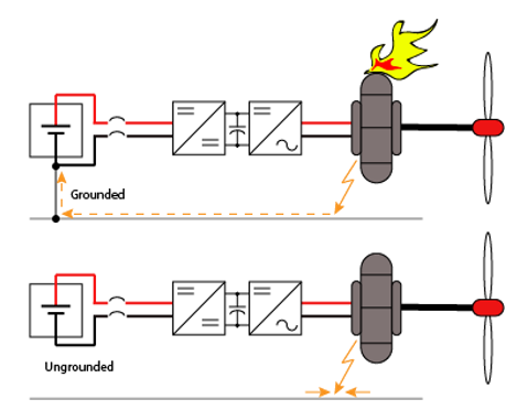
Figure 1 illustrates the difference between a grounded versus ungrounded power system. In case of a fault between an electrical portion and the frame, the current will take the path of least resistance and attempt to return to the power source where it originated. In the case of grounded power, this path is clear. A low ohmic negative-to-ground bonding jumper ensures a standard resistance route back into the battery. The resulting current is limited by the fault resistance only and can instantly reach hundreds of Amperes. As follows, overcurrent devices will generate heat and possibly a fire, which is unacceptable onboard an airplane. On the contrary, the ungrounded system poses an insurmountable high resistance route back into the battery due to its missing “negative to ground” bond (NG bond). Hence the resulting currents on a first-fault basis are minuscule, and the system will keep operating. A second fault, however, will take the system down, which is why it is recommended to service an ungrounded system as soon as possible after a first fault has occurred. This means an increased chance of reaching ground under power for the airplane operator instead of suddenly facing a dead-stick landing situation.
Bender devices in electric airplanes
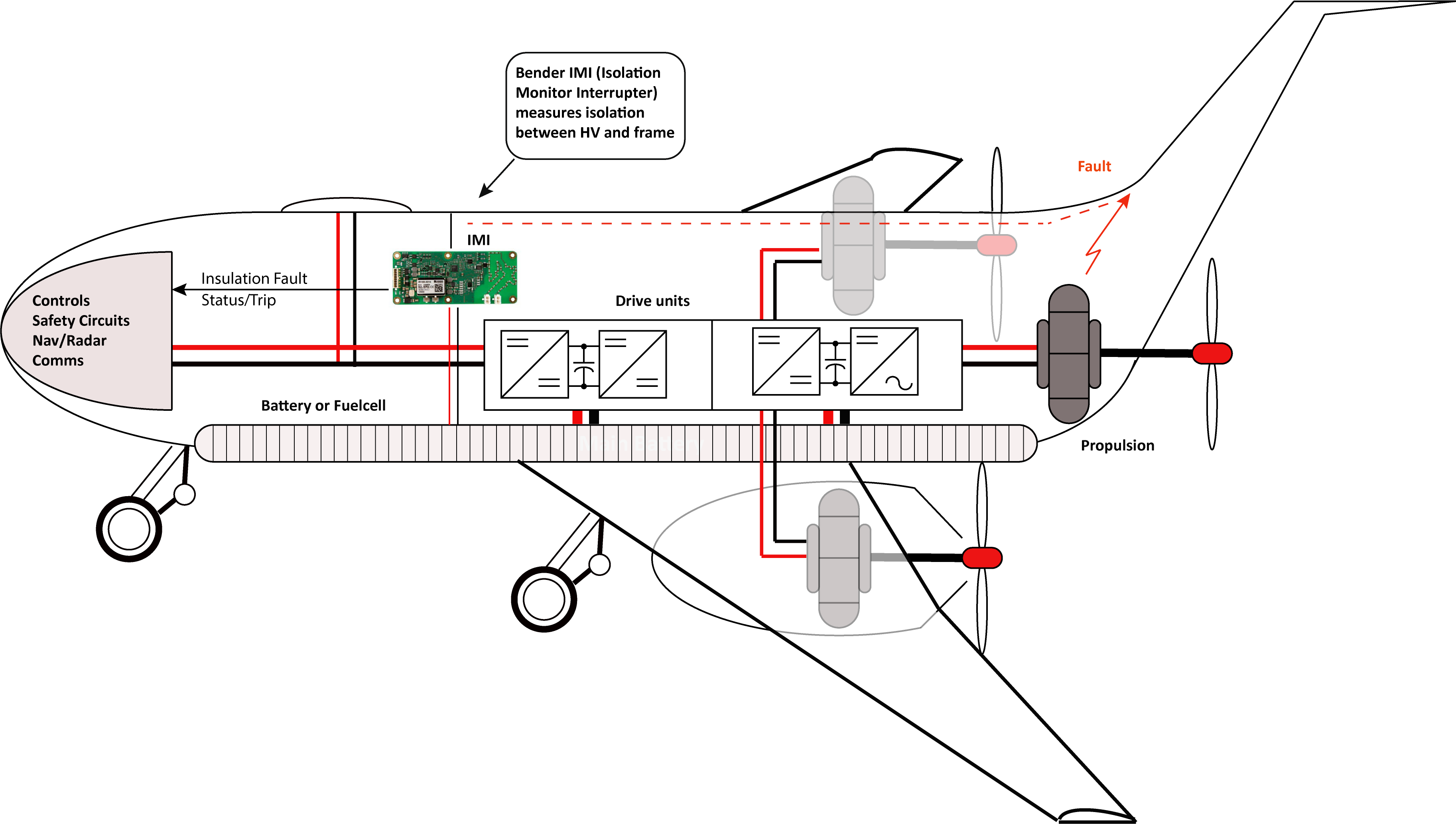
To ensure that the operator is properly notified about the status of his ungrounded power system, a special monitoring device is required. Isolation Monitoring Interrupters (IMIs) or Ground-Fault Detection Systems (GFDSs) have been employed to monitor ungrounded power systems for decades. In their simplest form, the common H Bridge has been around since the 1950s. Nowadays, power systems have matured to a degree where a simple measuring circuit is no longer adequately equipped to effectively monitor accurate isolation values. There is power conversion, followed by heavy utilization of rectification and high frequency switching involving IGBTs. There are also intended ground connections via Y-caps and filter circuitry. Mix that with voltage variances due to constantly changing load and charge demand, and the need for a sophisticated IMI circuit and algorithm becomes apparent. Bender IMIs couple onto the HV system via pilot wires. They generate an internal measuring signal that superimposes onto the HV rails from where it penetrates the entire vehicle’s electrical system. These IMIs monitor for isolation break downs in terms of Ohms. The less Ohms there are, the more the system is compromised. It is up to the HV system design team to determine what the adequate thresholds are at which the IMI starts to alert the operator of a dangerous situation. Usually though, a conservative figure is chosen to allow for ample pre-warning and layers of safety.
In conclusion, modern IMIs play an integral role in ensuring continuous uptime and safety of an ungrounded, airborne power system. The ungrounded system is only reliable if it remains ungrounded. First faults can be detected quickly and fixed before a more devastating second fault occurs. When you combine this with the ability to trend isolation deterioration over time, the IMI becomes the tool of choice to ensure safe flying.
For more information about this application or to learn more about Bender technology related to your specific application, contact our team of experts.
This article is for informational purposes only. Bender provides the information "as is" without warranty and is not responsible for its accuracy or reliability. No warranties are given regarding its suitability for any specific circumstances.


.jpg?width=352&name=Blank%20300%20x%20175%20(21).jpg)