Battery Energy Storage Systems (BESS) – Potential in System Design
In order to take advantage of the inherent benefits of an ungrounded system (such as high availability and improved fire protection), it must be planned into the original system design. This planning decision is simplified by the fact that a transformer can be used in industrial Battery Energy Storage Systems due to a higher output (e.g. 500 kW) or when connected to a higher voltage level, thus isolating the BESS galvanically from the main distribution. In addition, the DC circuit between the battery and the inverter is usually designed as an ungrounded network.
How ungrounded systems work with battery energy storage systems
A characteristic of an ungrounded system is that the active conductors have no connection to ground. Enclosures of the electrical systems are still grounded. Figure 1 shows the simplified schematic structure of an industrial battery energy storage system - consisting of the core components batteries, battery management system (BMS), inverter and transformer. All yellow components concern the monitoring technology.
The electrical network is designed as an ungrounded system. The active AC and DC conductors have no connection to the ground. Note: The grounding of the devices is not shown here.
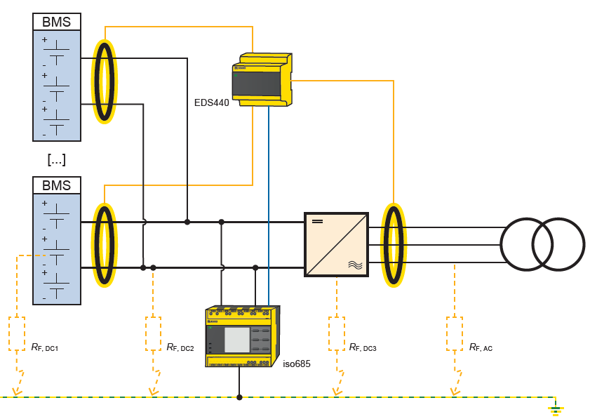
Battery modules are connected in series and combined in so-called racks. The series connection results in a higher system voltage. The parallel connection of several racks increases performance and storage capacity. The three-phase inverter performs the bidirectional conversion of the energy (DC<->AC) and is, in addition to the battery itself, decisive for the power flow and performance.
The use of a transformer is characteristic both due to the connection to a higher voltage level and due to the higher power (500 kW). Finally, this reduces line losses as well. The transformer galvanically insulates the battery energy storage system from the connected mains. Usually, the DC circuit between the battery and the inverter is designed as an ungrounded network.If grounding is provided, this is usually done at the transformer. However, it is recommended that the AC circuit between the inverter and the transformer is not grounded. In some cases, this is already specified via the transformer switching group, e.g. Dd or Yd. This creates an ungrounded system for the entire battery energy storage system. As explained below, this ungrounded system offers higher availability and improved fire protection for the BESS.
In addition to the core components, Figure 1 also shows the possible fault locations to ground. Faults to ground may occur:
- In the AC circuit between inverter and transformer
- In a cell or series connection of batteries
- In the DC circuit between battery and inverter
- In the DC bus of the inverter
The first fault in an ungrounded system establishes a connection to ground. Depending on the value of the fault and the insulation level, the phase-ground voltage of the faulty conductor decreases on the one hand, and the phase-ground voltage or voltages in the healthy conductors increases on the other. In the extreme case of a saturated fault, the voltage drops to almost 0 V and the voltage increases to the line-line voltage. Due to the grounded connection not being carried out, no circuit can occur during the first fault. The system can still be operated despite the first fault.
What are the benefits of using this kind of system?
Some benefits of this type of system include reduced downtime and improved fire protection for the BESS. High availability is guaranteed by the fact that the first fault to ground does not cause the system to shut down. A ungrounded system can theoretically be operated up to the second fault. In practice, however, this time advantage is used to find the insulation fault during operation, for example by means of an EDS and then to eliminate it, during proactively planned maintenance.
Improved fire protection compared to a grounded system is achieved by the fact that no fault current flows or can flow at the first fault. In a battery energy storage system, an impulsive load of the batteries with a high fault current, even if only short-term, is thus avoided.
For more information about this application or to learn more about Bender technology related to your specific application, contact our team of experts.
This article is for informational purposes only. Bender provides the information "as is" without warranty and is not responsible for its accuracy or reliability. No warranties are given regarding its suitability for any specific circumstances.