Ground Fault Monitoring for Battery Energy Storage Systems (BESS)
.png)
What are Battery Energy Storage Systems?
Battery Energy Storage Systems (BESS) are rechargeable battery systems that store energy to be used at a later time. During the day, clean solar energy is used to charge the battery storage system. These systems are typically used to cover peak load coverage and provide grid stabilization.
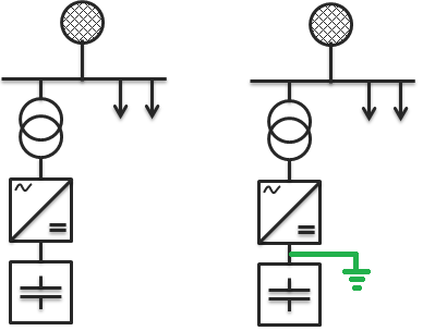
Grounding schemes of a BESS
There are two types of grounding that are currently being used with BESS.
- The ungrounded system - more common and has all system conductors isolated from ground.
- The grounded system - less common and ties a system conductor directly to ground. This can be the + conductor, - conductor, or neutral point within the inverter.
Why is the ungrounded system more common?
A solidly grounded system has one conductor tied to ground intentionally, which serves as the return path for current during a ground fault. A single ground fault on a grounded system will generate high amounts of ground fault current, which is why the BESS must be robust and resilient. This high current will either shut the system down or cause system failure, most commonly via a fire.
The ungrounded system does not have any conductors tied to ground, henceforth there is no return path for current during a first fault. The BESS can continue to safely operate during a first fault in an ungrounded system.
Dangers of an undetected ground faults
Although the system can continue to run during a first fault, it is vital that the fault is cleared as quickly as possible. If a second fault were to develop on the opposing conductor, a phase to phase or line to line short would be created through ground.
Imagine a scenario in which one fault has developed and there is a high ohmic fault on the opposing phase. This may not generate enough current to trip over current protection, however, it can generate enough power to cause a fire. Unfortunately, this exact situation is not just theoretical, it has happened in numerous solar and BESS installations.
How to detect and locate faults
Now that we understand the dangers of undetected faults, let's discuss how to properly protect against them. In a solidly grounded installation, a Bender DC sensitive residual current monitor can be used. These devices can detect leakage currents within different parts of the BESS, including at the module, pack, container and/or inverter. In an ungrounded installation, a Bender insulation monitoring device (IMD) can be installed to detect faults between isolation points. This would most commonly be from the battery to the first isolation transformer. Furthermore, a ground fault location system can also be installed to automatically locate and isolate the fault to the desired level.
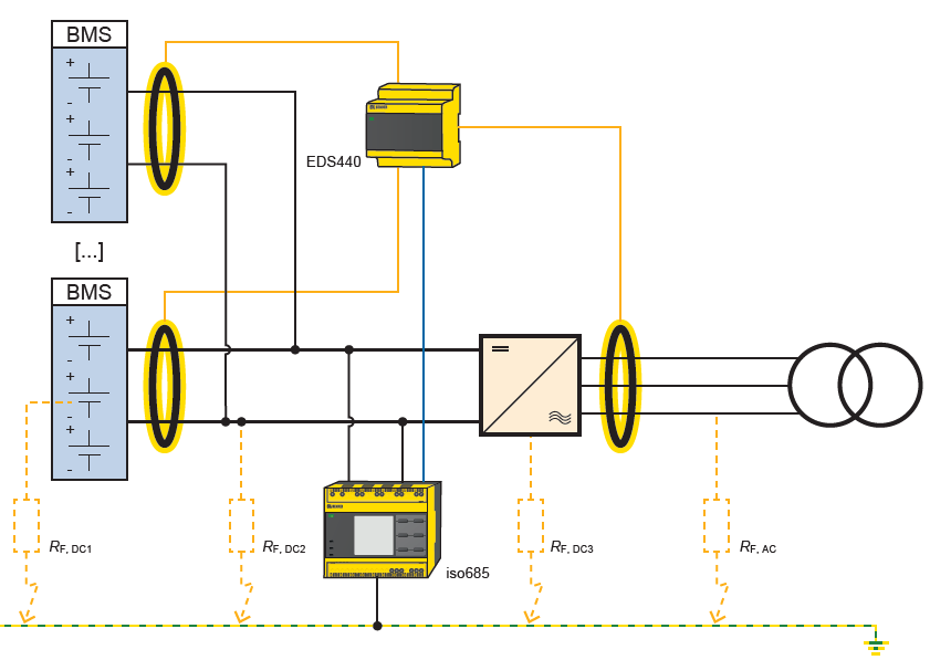
Figure 2 shows an example of a common ground fault location and detection system on an ungrounded BESS. The Iso685 will detect ground faults and assist with the location. The EDS440 unit connects to up to 12 current transformers to look for the ground fault location pulse coming from the Iso685. A ground fault anywhere on the system will be detected by the Iso685 and located by the EDS440 if it is within either of the battery containers or on the AC bus.
Common energy storage voltages and ground fault considerations
BESS DC voltages can drastically vary depending on the configuration of the batteries and the application. For example, a small home scale system may carry a DC bus voltage of 300VDC. A large utility grade BESS may operate at 1500VDC. There are also many installations in between that operate between 700-1100VDC. It is important to determine the maximum DC voltage so the correct ground fault detection and location device can be selected.
Let’s use a real-world example based off Figure 2. My DC bus voltage is 1200VDC and my AC bus voltage is 480VAC. I want to fault locate to each battery rack as well as on the AC side of the inverter. I must select an insulation monitor that is capable of fault location on 1200VDC, so I will select the IsoPV1685P. If my bus voltage was instead 700VDC, I would be able to select the Iso685-D-P. Now let’s assume that I do not want to add fault location, but I simply want to detect ground faults. Depending on the system size, I may be able to select the IsoPV425 instead.
As you can see, ground fault monitoring and locating on BESS does not have a “one size fits all” solution. It is vital to speak with an industry expert to determine the correct implementation and devices to use for a safe and reliable BESS. Don’t let a ground fault compromise your system safety. Speak with a Bender representative today for additional information and assistance.
For more information about this application or to learn more about Bender technology related to your specific application, contact our team of experts.
This article is for informational purposes only. Bender provides the information "as is" without warranty and is not responsible for its accuracy or reliability. No warranties are given regarding its suitability for any specific circumstances.