Power Generation & Frequency in the Modern World
Understanding Electrical Drives
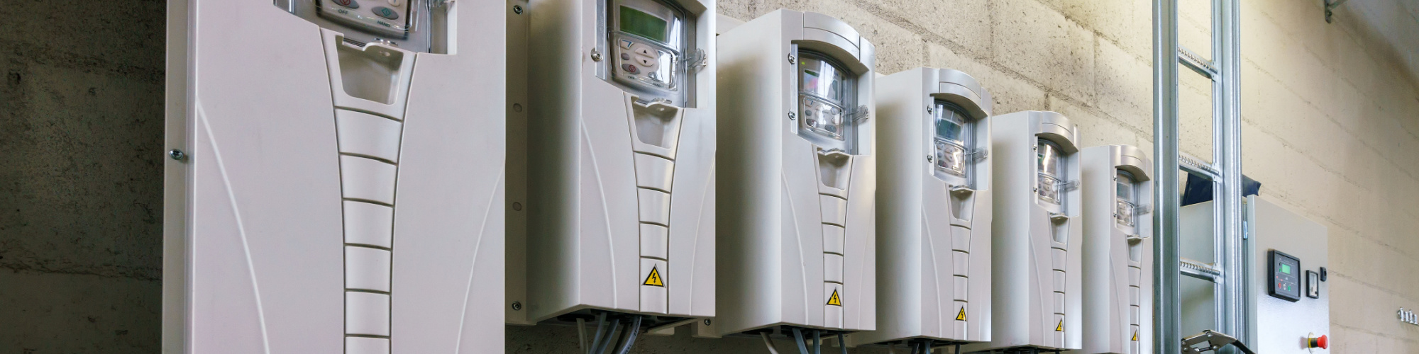
Electrical drives have found their way into every industrial application which has motors and movement of personnel and material. Hardly anyone can find a motor circuit nowadays that is not equipped with a drive. The most common variant here is the variable frequency drive (or VFD). Why variable frequency? Let's dive into this complex topic.
Intro to Basic Power Generation
The majority of residential and industrial power systems run on alternating power or short "AC". AC power is generated when you have a magnetic field cutting a wire in a swift motion. You could try to replicate this by holding a magnet and wire in your hand. The results would be minuscule, so you'd have to employ a sensitive meter to pick up small amounts of current generated. The way to experience greater measurable power is by using stronger magnetic fields, sitting on a rotating shaft, and cutting a multitude of wires (coils) that are wound in a specific fashion, resting in a stator. This arrangement of a turbo generator may have the size of a small submarine and can easily produce hundreds of Megawatts of power. Take a few of those in parallel, add boilers, steam generation, and cooling towers, and you have a full-fledged power plant.
Now, note that earlier we mentioned there are magnets (fields) on a rotor hitting stator coils with their magnetic field. We actually said "cutting," but that does not mean cutting in a literal sense, it means that the magnetic field is rushing through the coil, hence producing electron flow. Imagine a magnet rotating and its field is rushing by wire coils, similar to a clock, where the magnet is the rotating hand in the center, and the coils represent numbers 1 through 12. This current flow is directional - we won't go into right-hand and left-hand rules here, but just note that the orientation of the magnetic field and the direction of the attack determine which direction the electrons go.

Frequency
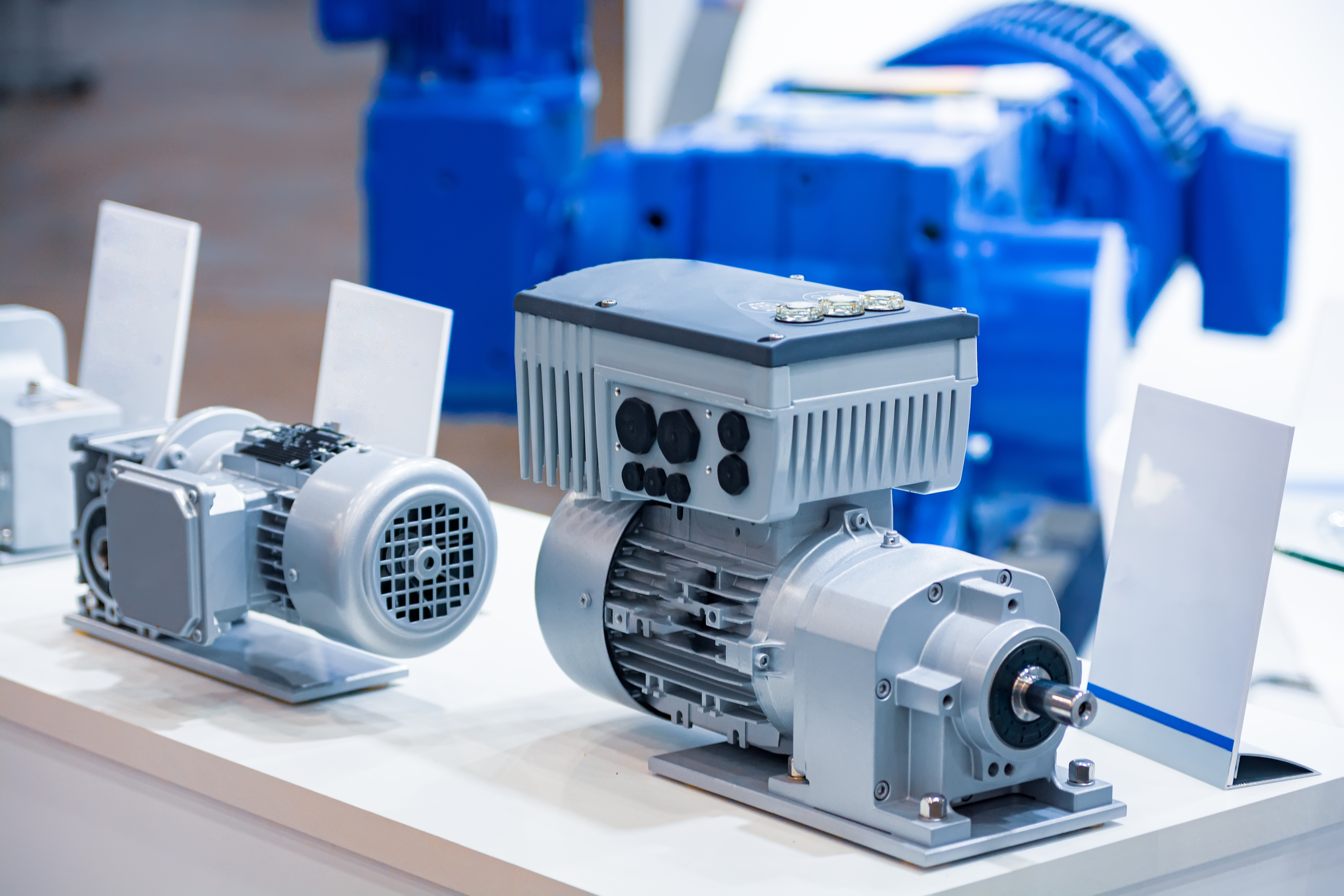
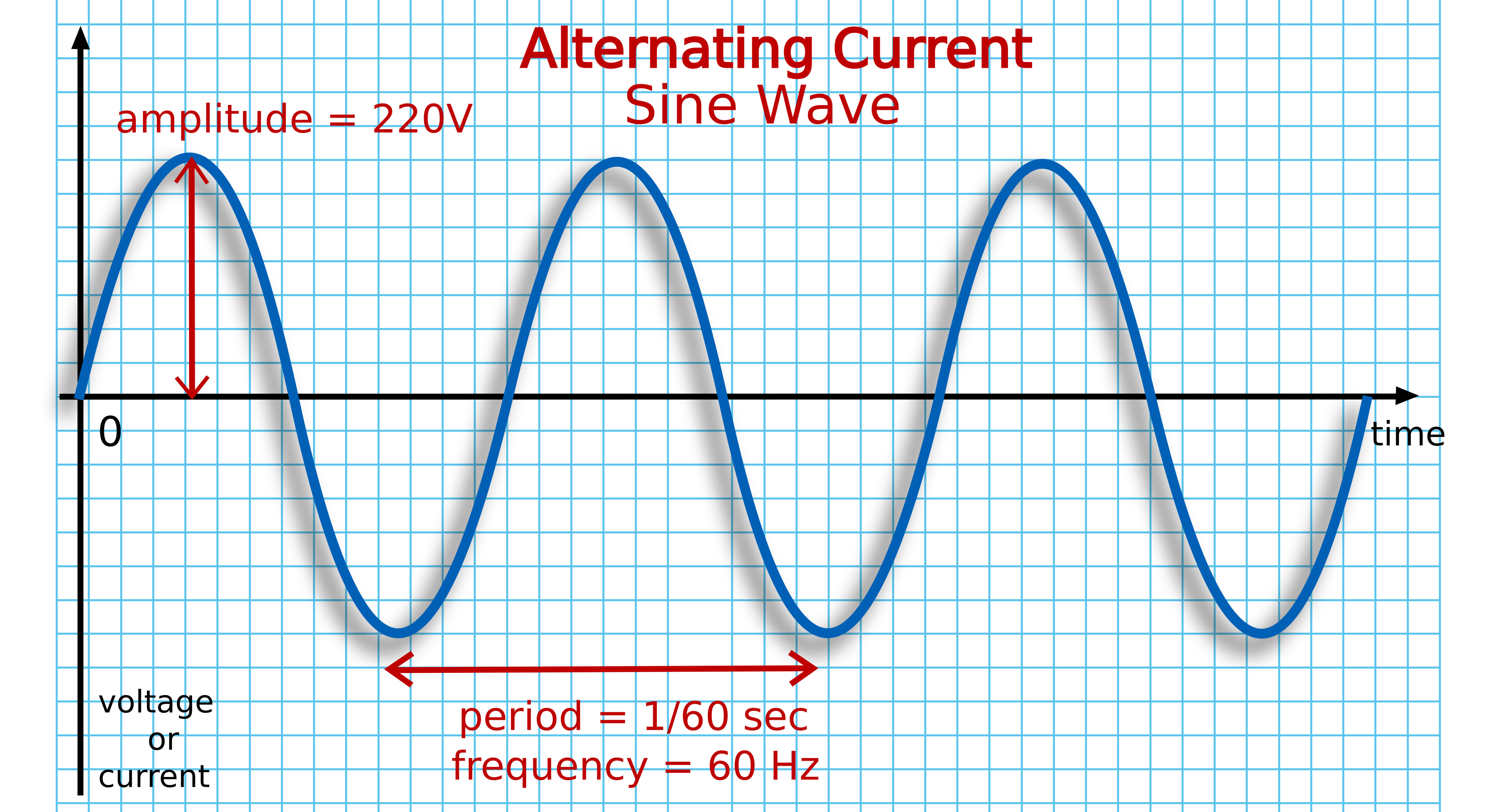
A magnet has a North and a South pole. Naturally, when a magnet rotates sixty times/second within the stator, the coils must knock electrons sixty times in one direction and sixty times into the other. This is called alternating current. It is also known as 60 cycles, or 60 Hertz, and represents our AC current grid frequency. This is important because a typical turbo generator may need to operate at 3600 RPM to hold this frequency steady. Our loads at home or in industrial applications employ motors that have, you guessed it, coils within them. The arrangement of the coils, their build, and their type determine their speed when exposed to 60-cycle current. The turbo generator may be a 2-pole-type (one North-South pair magnet) needing 3600 RPM to make 60 cycles. An industrial motor whose coils have been wound in a similar two-pole fashion would henceforth turn at 3600RPM. A 4-pole motor would turn at half (1800 RPM) and an 8-pole motor at 900. So we can see that pole count, frequency, and RPM are deeply intertwined. For the longest time since the first AC induction machines came online, this is the relation that was.
Bender's Solution for Frequency Monitoring
Bender carries several devices in our portfolio to ensure that the frequency stays within its allotted limits. The VMD460 is a device that performs monitoring and alert functions for frequency, phase rotation, and voltage. Another model worth mentioning in this realm is the VME and VMD420 family. These are powerful electronic control relays that fit in the palm of your hand. While small in size, one can program them to alert when the frequency should leave the sixty-cycle range.
Why is this important? Well, if the grid frequency fails, then this will have a direct impact on motor speeds and grid stability.
Motor Speeds
Immediate notifications are a must. Back in the early days, processes were running at pretty static speeds with little-to-no speed modification until the VFD arrived. The VFD is a purely electronic device with the sole purpose of altering the frequency from the powerplant to a varying frequency to be employed on the motors we use. If you can switch the frequency from 0 to 60 cycles in a seamless manner, then the motor's speed can be fully adjusted from virtually zero to full speed. This poses an incredible advantage for processes in all walks of life. Take elevators, for example, that start smoothly, come up to speed midway, and slow down just in time before the 50th floor. How does the VFD do it? It is connected to a power source coming from the grid at sixty cycles. Internally, the 60 cycles are being rectified into direct current and smoothed out. The direct current is then fed into transistors which will modulate the DC into a varying hertz waveform that you, the operator, desires for the application.
To stick with the above examples, a 4-pole motor would be running at 1800RPM at 60 cycles. Reduce that to 30 cycles, and the motor runs now at half speed. Reduce to 6 cycles, and the motors do only 180RPM. This can be played up and down the scale to a degree where certain drives may even be able to overspeed and produce frequencies in excess of 60 cycles. Beware, though, of destroying the motor when running at excess speeds. It is important to note that with the introduction of the VFD, the electrical/industrial community had to adapt not only to motor technology, but also to secondary devices that are related to measurements and safety.
For the longest time, the industry measured amps, volts, and power in a stable, sixty-cycle environment. When this is no longer a given, how do the various instruments react in the field? The discussion on this would be endless, but we shall pick a device our company employs frequently as an example. Bender manufactures ground fault relays to protect people and machinery from hazardous currents. If there is an electrical current leaking to ground, we indicate an alert. Sixty-cycle ground fault relays are relatively simple and depend on a single coil to detect current. Note again, this coil is designed and optimized for sixty cycles, with some leeway up or down. What happens if this coil experiences 20, 10 cycles, or even DC? It is out of its operational range, and the reading may be off or can no longer be trusted.
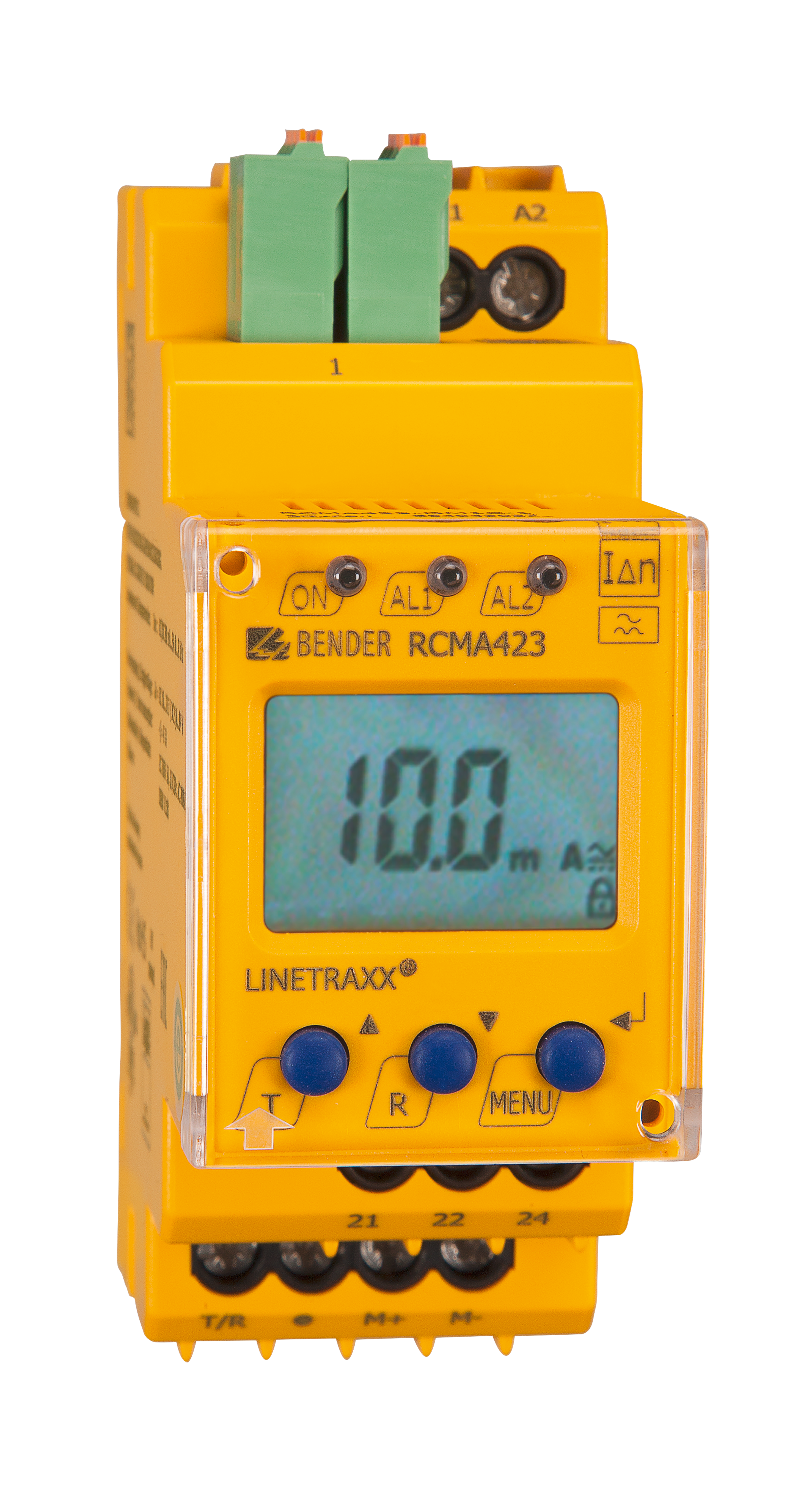
The industry needed to adapt so Bender designed a family of RCMA and RCMB ground fault relays that have a coil technology implemented that will adapt to varying frequencies and ensure adequate readings. As you can see, it is necessary for a technology company to keep up to date with the ever-changing developments in electrical power. Our core competency is well represented by our ability to monitor for frequency, current, voltage, power quality, insulation, and ground fault currents.
For more information about this application or to learn more about Bender technology related to your specific application, contact our team of experts.
This article is for informational purposes only. Bender provides the information "as is" without warranty and is not responsible for its accuracy or reliability. No warranties are given regarding its suitability for any specific circumstances.